This is going to be a bit of an exploration into some of the design decisions I made when constructing the RCBus OPL3 soundcard.
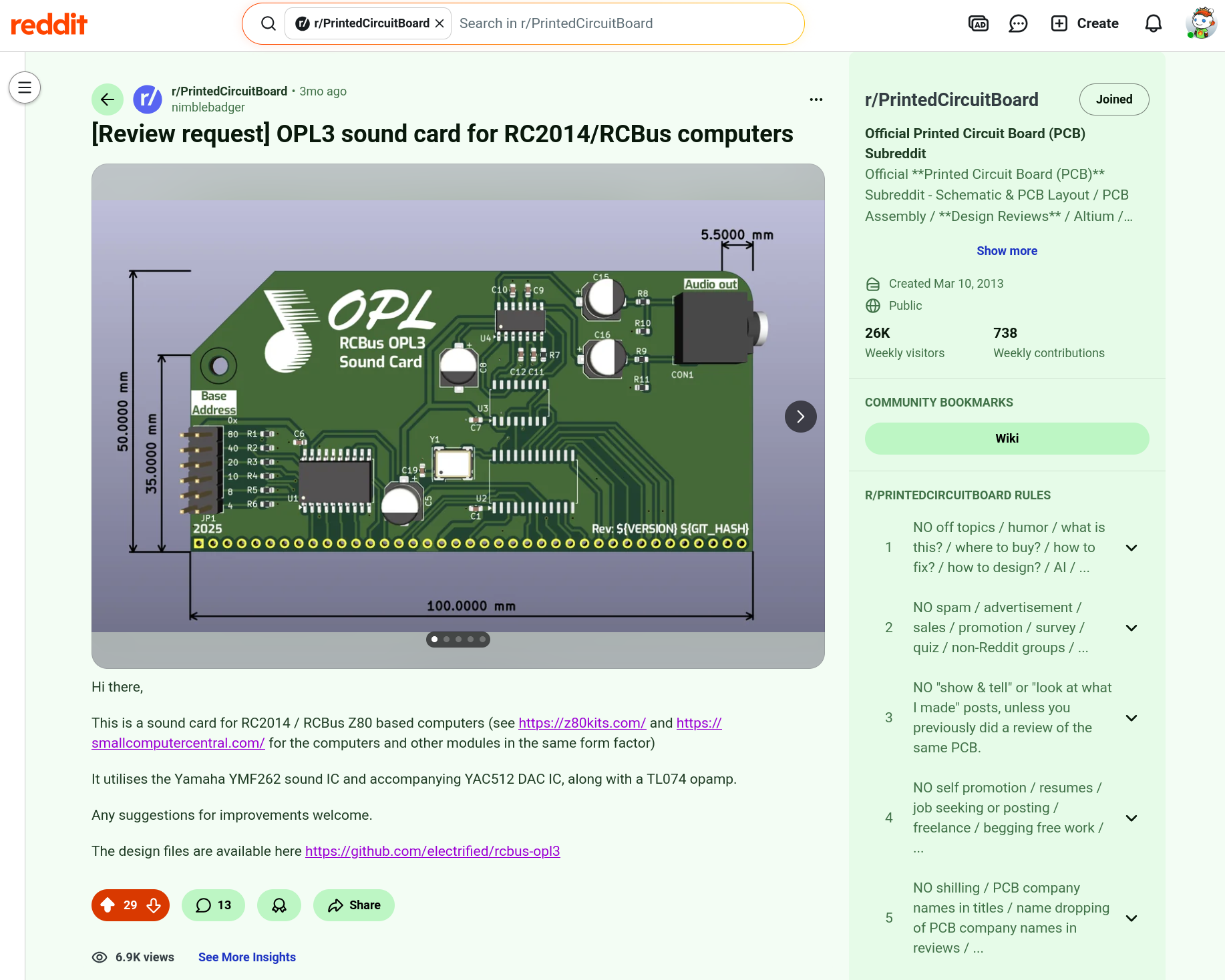
If you’re after details of the board or instructions on how to build and use it, see the project page here
Project inception #
I was contacted back in July 2025 by Joao who had been using my YM2151 sound card, asking if I had any intention of creating an OPL2 or 3 sound card for the RC2014. At the time I had been out of the RC2014 scene for some time, tinkering on other projects or generally being occupied with family life. An OPL sound card sounded like a great ide though, so I leapt at the chance of creating one! Thank Joao for nerd sniping me into working on this project!
Initial project direction #
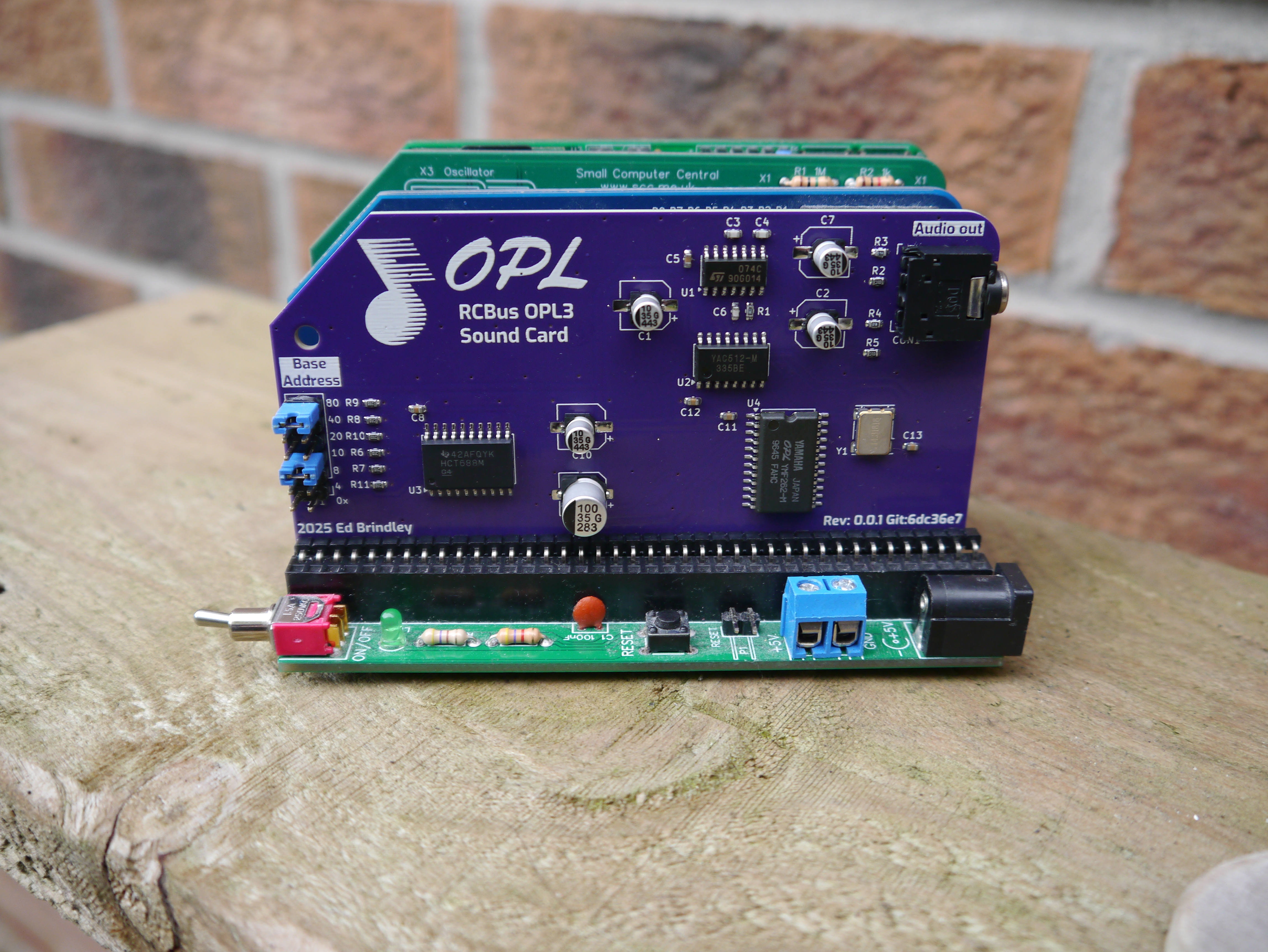
Initially I started work on an OPL2 board, however Joao suggested we go with the OPL3 as this is more advanced and has a stereo output. As the OPL3 is a surface mount IC this drove the decision to make as much as possible of the rest of the board surface mount as well. For manufacturing ease I tried to use 0604 surface mount resistors and capacitors as those are within the basic tier at some PCB assembly houses. The components are all on one side of the board as well to aid soldering and assembly using solder paste and a hot plate.
Choosing the opamp #
The YAC512 DAC requires four opamps so a quad channel opamp IC is required. I chose to use the TL074, this is a classic opamp which has been bettered by more modern designs but it’s often used by OPL3 sound cards and is therefore proven. As I am definitely not an op-amp expert when it comes to choosing an opamp with the correct parameters, I decided to go with a tried and tested IC. While researching opamp usage I did incorporate a couple of ideas which I previously wasn’t aware of in terms of good practice one of those is having a resistor to ground on the output after the decoupling capacitors and the other is having a small value resistor in series with the output.
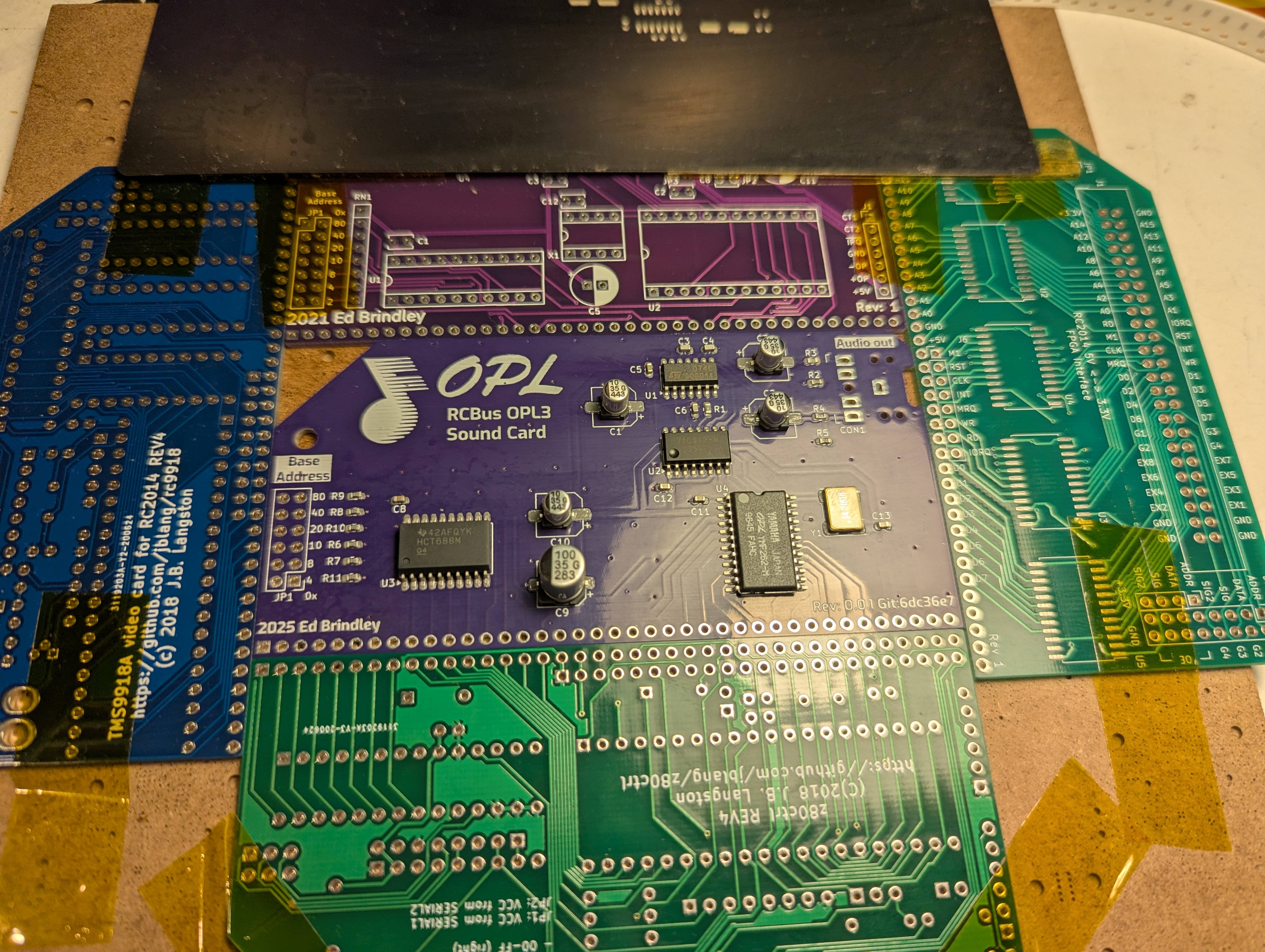
A cosmetic decision I had to make was whether to use the RCBus board specification or the RC2014 board specification. In the end I decided to go for the RC2014 design over the RCBus design simply because it matches all the existing boards I already have.
Breadboarding #
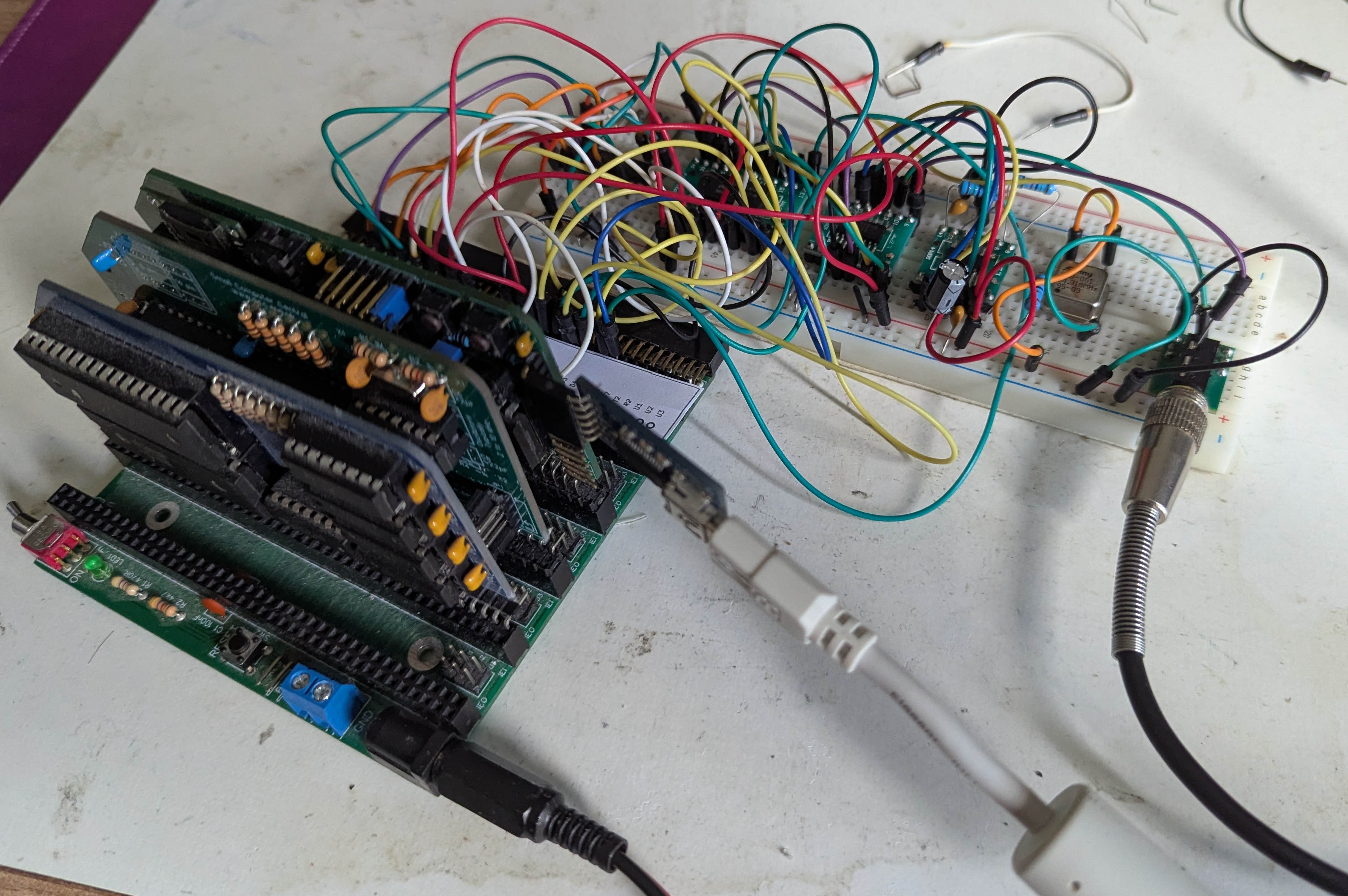
Before getting a PCB manufactured I wanted to prove the design out on breadboard. This was partially due to wanting to understand how the op amp operated on a five volt supply and to experiment with different components only use in the output circuit. As we are using surface mount components using breadboard is made somewhat more difficult, requiring the use of adapter boards to allow SMD components to be used on the breadboard.
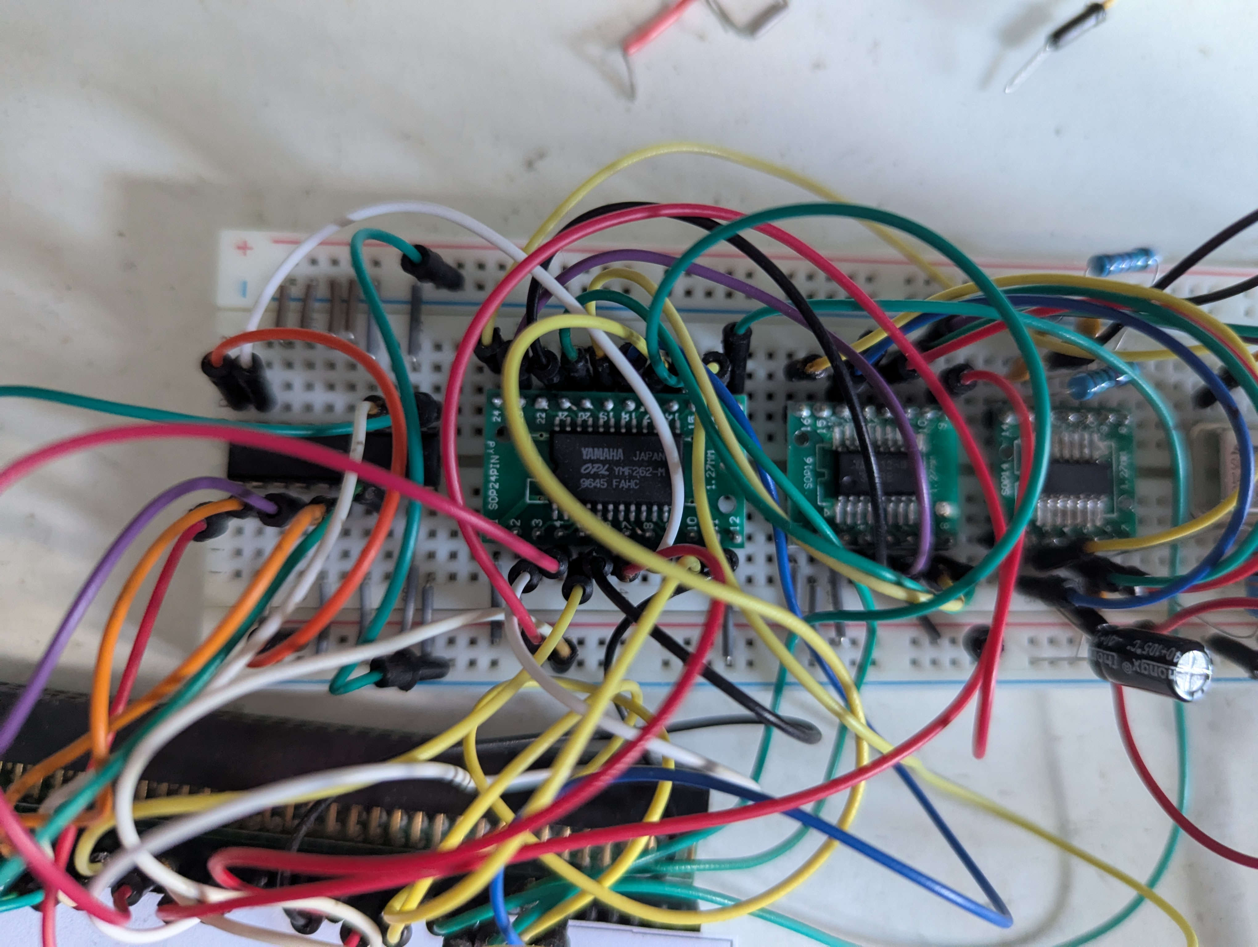
Even though it was a time consuming process I do appreciate the breadboarding stage as it gave me longer to think about the design, do research and incorporate suggestions which improved the design.
Peer review #
Another aspect to the design process which I’ve not done before was getting a peer review for my PCB design. I posted the board up on the printed circuit boards subreddit and solicited reviews. This resulted in quite a lot of useful information and suggestions which I incorporated. Some of the suggestions were things that are fairly obvious but I had just been resisting, such as rotating the main IC to enable better routing.
Initially I’d placed all the ICs with pin 1 facing the same direction just for uniformity but there was those no electrical or engineering reason to do that, so the review process was a useful as I abandoned some of these misguided design choices. Another choice was made to use through hole components for the address jumper pins, RCbus header and the line out socket. This may be something I revisit on future designs but all of these were parts I already had in stock so it made sense to use the parts already have. Also some mechanical strength is useful for those parts as they are subjected to loads when inserting and removing the board and inserting and removing the audio cable.
Assembly #
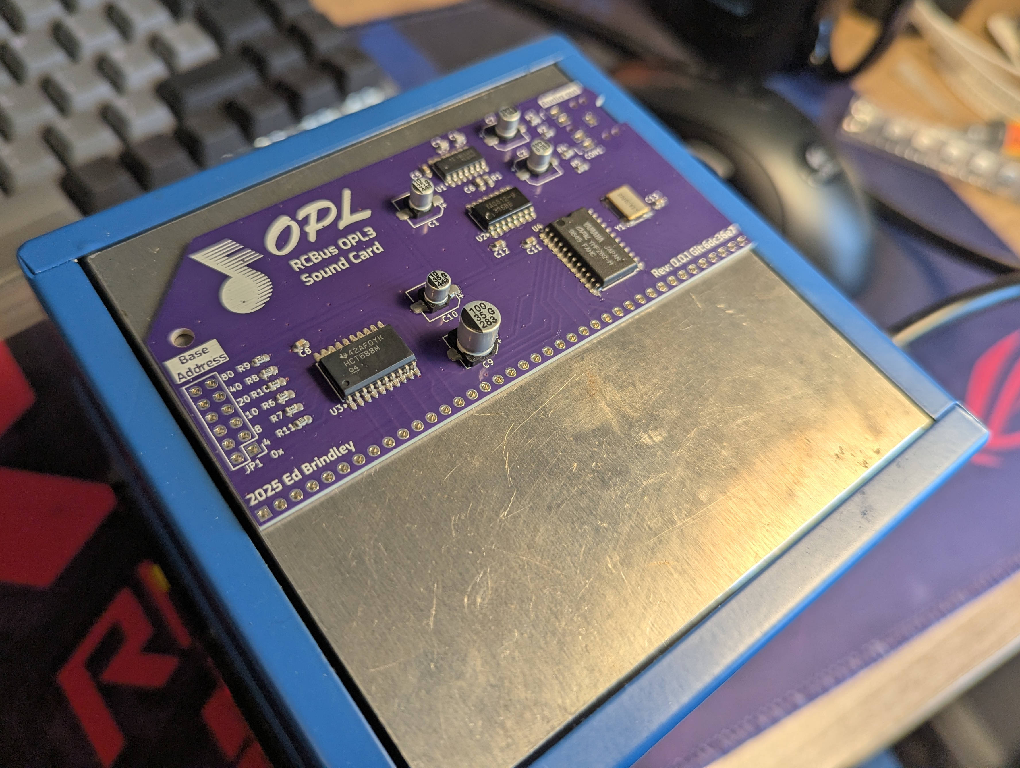
As previously noted for soldering I chose to do this on my small hot plate applying solder paste with a stencil also provided by PCBWay. This proved very successful especially when when I gave up using my out-of-date solder paste that I’ve had that I’ve kept on refrigerated for some years!
Licensing #
Another decision I had to make was what licence to use, previously I’ve used the CERN open hardware licence however this does not seem to be as widely used as it was some years ago. Not being a legal expert I wasn’t exactly sure which licence to choose however I eventually went for the creative commons share a like license. Some other RCBus designs are using this license such as Alan Cox (etched pixels) designs. Going forwards when I do a second revision of the board I’m planning on applying for an open hardware designation and may put the logo for that on the board as well.
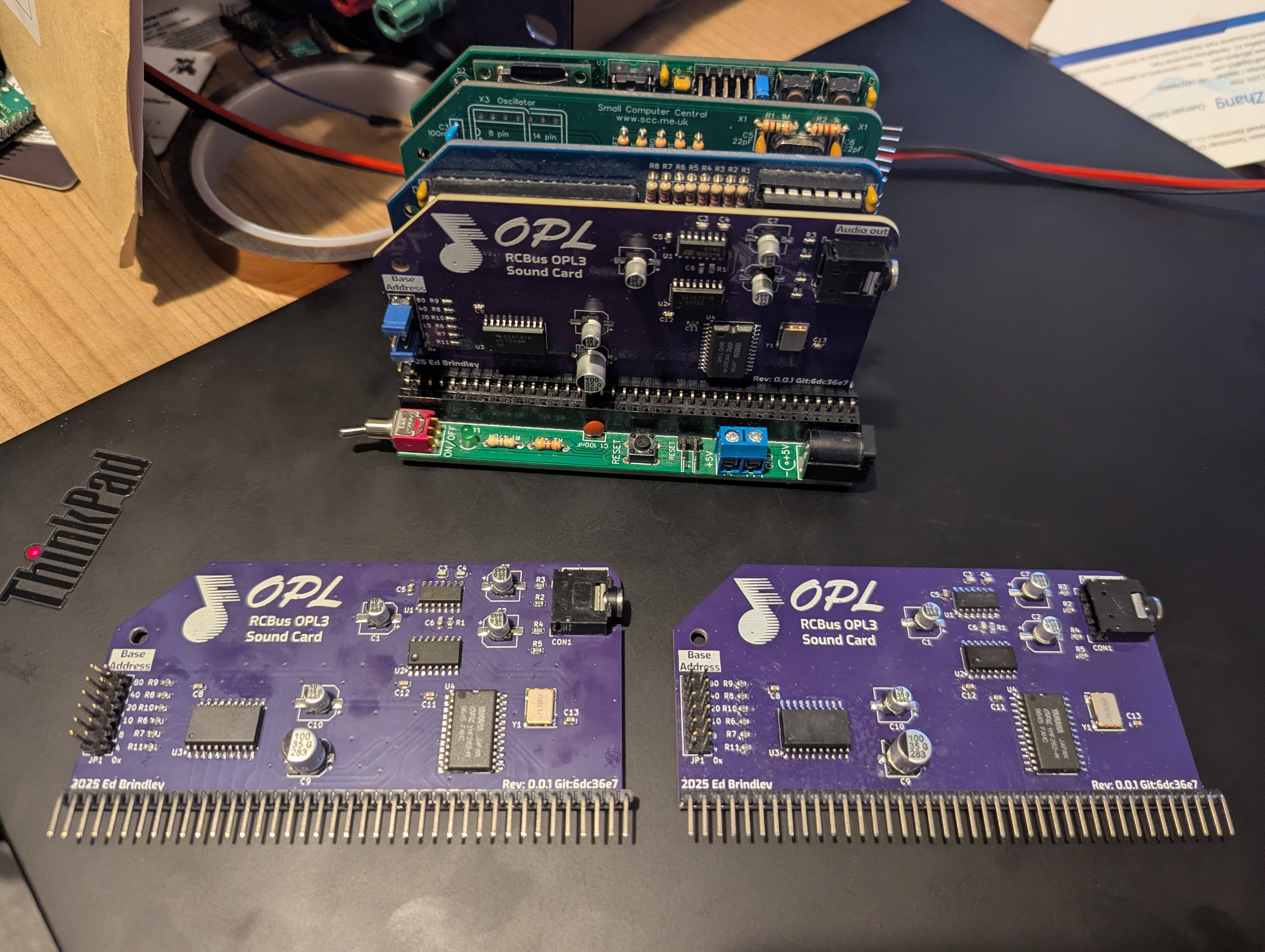
First board revision results #
The first revision of the boards I’ve received I am relatively happy in that there are no major issues other than a small number of incorrect footprints. The incorrect footprints are for two of the electrolytic capacitors where the footprints are too large, but this does not prevent soldering, and the main YMF262 IC where the footprint used is not wide enough. This is because it seems that the YMF is not a standard SOP24 width. For the second iteration of the board I will use a custom footprint.
Another aspect of this project that I’ve been quite happy with is my use of Kibot to produce a github pages site from the Kicad sources. This produces an easy to use BOM which is very useful when constructing the PCB. It also outputs gerbers and can replace placeholders on the PCB which I have used to place the version number and git hash on the board.
Farnell woes #
The only negative on this project that I’ve experienced have been due to sourcing the components from Farnell. I chose them because I have used them successfully in the past and they stocked all the components that I required. Unfortunately two of the line items on my order were mis-picked: one set of surface mount capacitors and one set of surface mount resistors. These items only cost pennies and I have been refunded, but when there is such a high delivery charge and small order charge getting a refund for the individual items is not much use as I will still have to place another large order. In the end I resorted to obtaining small quantities of those parts from an eBay seller. I think going forward I will probably stop using Farnell and return back to using Mouser as I think they also stock all of the needed components. This is a shame as I like to use a locally based, if not owned company such as Farnell based in Yorkshire. I should also say that the customer support experience reporting these misspicked components was very poor. When I spoke to them on web chat the first person I spoke to initially was not technical and transferred me to another chat handler who then was also unable to answer my request and asked me to use submit a an email to their tech support email address. This email was not answered for a number of days and when it was the answers almost seemed AI generated and not very serious considering I was complaining about the nature of their service.
What next? #
As previously stated, there were a couple of minor footprint issues on the board which I would like to resolve with a 2nd spin. Additionally I may return to the OPL2 design as I have all the parts for it, and it may be liked by those who are allergic to surface mount technology!