Why IceStorm? #
The Lattice ICE40 FPGAs are the first to be supported by an fully open source toolchain - [Project IceStorm by Clifford Wolf] (http://www.clifford.at/icestorm/)
After previously owning a Xilinx based Digilent FPGA board and getting fed up with the bloated ISE software, I was keen to try IceStorm.
The IceStorm toolchain has a number of benefits over commercial vendor tools:
- Not limited to specific operating systems or architectures, so for example can be used on a Raspberry Pi
- Small download size
- Easily scriptable via your favourite build system e.g. makefiles, scons etc
- The ICE40HX4K is only limited to 4K LUTs via software, internally it has the same die as the 8K part - using IceStorm allows it to be used as an 8K device!
The hardware #
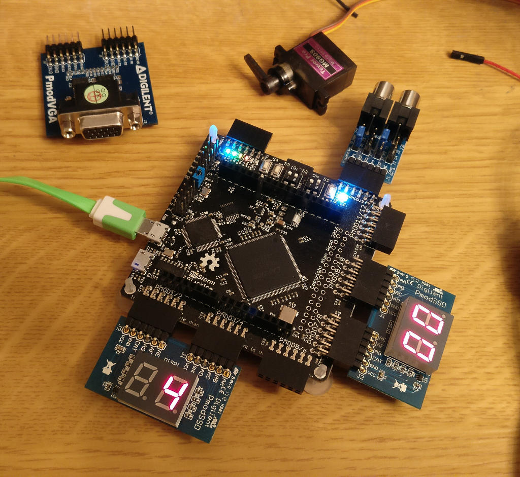
I purchased a myStorm BlackIce board, which has an ICE40HX4K FPGA. It has 512KB SRAM, 2 buttons, 4 switches, and an SD card slot. Additional hardware can be attached via PMODs which are an open connector standard from Digilent. The myStorm BlackIce board has six double PMODs and two single PMODs.
Other ICE40 boards are available but the BlackIce is Open Source Hardware, has quite a versatile design and is also inexpensive at around £40.
To complete the examples in the book I bought the following PMODs to provide the necessary additional hardware:
The book #
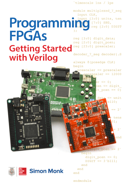
Scouring Amazon for a beginner’s guide to Verilog, I came across Simon Monk’s Programming FPGAs - Getting Started with Verilog. Most other Verilog books either use outdated Verilog syntax or are massive tomes not aimed at beginners.
Below are my notes on the book, chapter by chapter for the changes I had to make to accommodate IceStorm and the BlackIce board. If I mention something, this applies to later chapters as well, but I won’t mention it again (e.g. the 100Mhz clock). The commands assume you are running Linux.
Getting Started #
I have a branch of Simon’s repository with my BlackIce modifications. I also built the examples using Lattice’s iCECube2, and the project files for doing that are also in there.
The specific connectors I had the PMODs connected to are left as an exercise to the reader (I can’t remember! A bit of trial and error or looking at the schematic should enable you to work it out ;-)).
The upload procedure is unique to the myStorm BlackIce board, however the other yosys/arachne/icepack commands will be similar for all ICE40 based boards.
Chapter 2 #
Instead of downloading ISE, follow the instructions here http://www.clifford.at/icestorm/ to install IceStorm. For text editing I found Visual Studio Code with Verilog syntax highlighting to be great.
You can also install the full suite of IceStorm tools using Apio which may be easier for beginners. apio-ide is an IDE based around Atom that may also be used. Your mileage may vary with these, I’ve not used them extensively.
Chapter 3 #
I skipped most of this chapter as I was mainly interested in learning Verilog. IceStudio provides schematic entry, although it’s still fairly experimental.
The buttons and switches on the myStorm BlackIce board are pulled up with external resistors and are active low.
IceStorm (and the proprietary Lattice iCECUBE2 tools) use PCFs (Physical Constraint Files) rather than the UCFs (User Constraint Files) of the Xilinx tools. The syntax is somewhat different, e.g for the myStorm board the UCF on page 46 becomes:
set_io Clock 63
set_io QA 71
set_io QB 67
set_io QC 68
set_io QD 70
Note that you will have to refer to the schematic of the board to figure out which of the FPGAs pins the buttons/switches/PMODs etc are connected to.
Chapter 4 #
To generate a bitstream you can upload to your FPGA, with your current directory being blackice/ch04_counter_verilog run the following commands from your shell
First use Yosys to synthesize, specifying the output blif file name and the input Verilog files
yosys -q -p "synth_ice40 -blif chip.blif" src/*.v
Then use Arachne to place and route the synthesized output (the -d and -P parameters will depend on the specific ICE40 on your development board)
arachne-pnr -d 8k -P tq144:4k -p src/counter.pcf chip.blif -o chip.txt
And finally use icepack to generate a bitstream you can upload to the FPGA
icepack chip.txt chip.bin
Connect the BlackIce board to your computer using the USB socket closest to the ARM chip, and run the following to set your serial port to raw mode and monitor the output from the board. You may need to be root to run this.
(stty raw -echo;cat) < /dev/ttyACM0 &
You should get back the last message the ARM on the board emitted, probably something like:
Programming from flash
Then upload the bitstream to your FPGA:
cp chip.bin /dev/ttyACM0
You should see some blinking of the LEDs as the bitstream loads, and pressing switch S3 should increment the counter.
Chapter 5 #
The myStorm BlackIce has a clock speed of 100Mhz, I therefore increased the width of the counter used by the debouncer.
The seven segment PMODs each have 2 digits. To get 4 digits connect 2 SSD PMODs to the myStorm and instantiate two instances of display_7_seg. Each PMOD has a single pin that determines the active digit dependent on it’s high or low state.
The digit segments are active high rather than active low and there is no decimal point position so there are only 7 elements instead of 8.
Chapter 9 #
The VGA PMOD is 12-bit colour, with 4 bits for each for red, green and blue. Make appropriate adjustments for this.
To accommodate the BlackIce’s 100Mhz clock, I took the 32Mhz Papilio design and added a prescaler to divide by 3. This was close enough to work on my monitor.